LeIsaac × Marble: Large-Scale Generalization and Customization of Embodied Environments
This tutorial walks you through how to integrate Marble-Generate scenes into LeIsaac, allowing you to build and evaluate diverse embodied tasks across large-scale generalized environments.
🎥Marble-Generalized Scene Sets
Step 1: Prepare the USD Scene
To add a custom scene in LeIsaac, you first need to prepare a USD-compatible scene using Marble.
1.1 Create a World in Marble
Navigate to the Marble platform.
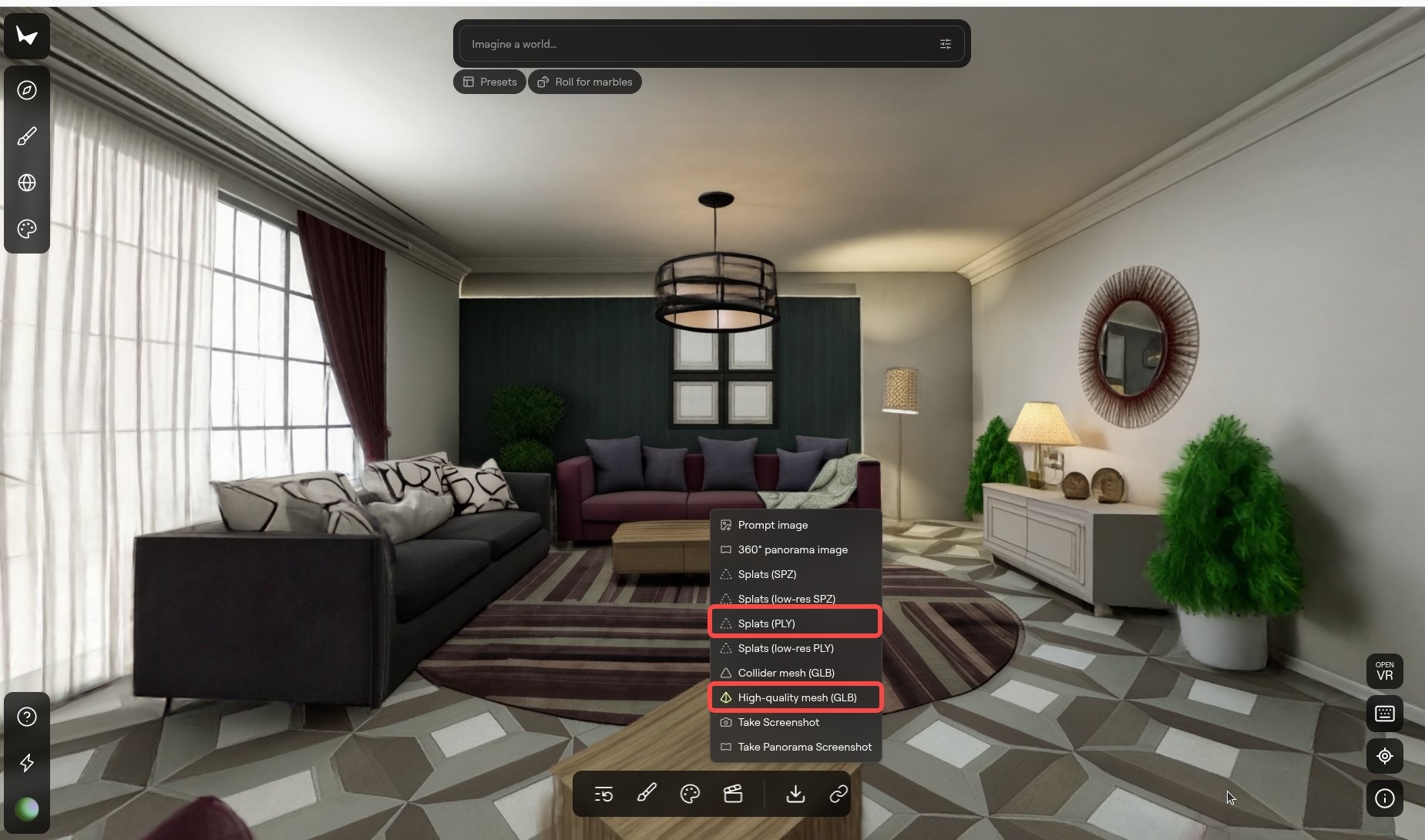
Follow the instructions in the Marble documentation to create your custom world model. Once you are satisfied with the result, download the following files:
- Splats file (
.ply) - High-quality mesh(recommended) (
.glb) or Collider mesh (.glb)
- For best results, please use high-resolution images or videos.
- It is recommended to refine and finalize the panorama before generating the full world.
- Real-world capture tips: Use an eye-level view, maintain a moderate distance, and capture the scene without occlusions. Avoid top-down or bottom-up angles and ensure objects appearing in mirrors are also directly visible.
- When possible, using panorama image usually improves spatial completeness, background continuity, and overall clarity. Panorama resources can be referenced at: PolyHaven, or you can capture your own multi-angle images and feed them into Marble.
1.2 Convert Splats (PLY) to USDZ
After obtaining the splats file (.ply), it needs to be converted to USDZ format using NVIDIA 3DGrut.
Install 3DGrut
Download and install the 3DGrut.
Follow the installation instructions provided in the repository.
If you encounter installation issues on RTX 50-series GPUs, this related issue might be helpful.
Convert PLY to USDZ
To convert splat data PLY format to USDZ format, run the following command:
python -m threedgrut.export.scripts.ply_to_usd path/to/your/splats.ply \
    --output_file path/to/output.usdz
1.3 Integrate Gaussian Rendering and Mesh Collisions in Isaac Sim
In this step, we combine Gaussian Splatting for high-quality visual rendering with mesh geometry for accurate physical collisions.The result is a single, complete USD scene as the background scene for the next step.
1.3.1: Load and Align the Gaussian Scene and Collision Mesh
- Begin by double-clicking the generated
.usdzfile to extract its contents. Locatedefault.usdain the extracted folder and drag it into the Isaac Sim GUI viewport to load the Gaussian splatting scene used for rendering. - Next, in the Stage panel, create an Xform at
/World/Xform, select it, and add a reference to thetexture_mesh.glbfile using an absolute file path. At this point, the scene should contain/World/gaussfor Gaussian rendering and/World/Xformfor mesh-based collisions. - Before adjusting the mesh, first ensure that
/World/gaussis aligned with the world coordinate system.Then align/World/Xformto match the Gaussian scene.Always ensure that the Gaussian splats and mesh geometry overlap correctly in the viewport.- In most cases, rotating
/World/Xformby 180 degrees around the Z axis is sufficient. Depending on the source data, you may also need to apply scaling (commonly ×100) or additional translation and rotation adjustments. - In this example,
/World/gaussis first rotated 180 degrees around the X axis, and/World/Xformis rotated 90 degrees around the X axis followed by 180 degrees around the Z axis to achieve proper alignment.
- In most cases, rotating
1.3.2: Configure Physics and Colliders for the Mesh
- After alignment is complete, configure physics on the collision mesh. Select
/World/Xformand add physics using the Rigid Body with Colliders Preset, then enable Kinematic in the Rigid Body settings so the mesh behaves as a static collision object. - Next, locate the mesh prim under
/World/Xform(typically/World/Xform/decimated_meshor/World/Xform/decimated_mesh/Mesh0, i.e., the prim whose Type isMesh).Under Physics → Collider, set the Approximation mode tomeshSimplification. This setup provides accurate collision behavior while maintaining good simulation performance.
1.3.3: Optimize Visuals and Export the Final USD
- For improved visual quality, you may optionally hide the mesh geometry and keep only the Gaussian splats visible, while still preserving the underlying collision volumes.
- Collision visualization can be enabled when needed for debugging or inspection.
- Once both rendering and collision behavior are verified, save the combined scene as a single USD file (for example,
scene.usd).This USD will be used as the background scene in the next step.
Step 2: Scene Composition for Tasks
Some manipulation tasks in LeIsaac (e.g., cloth folding, toy cleaning) are executed on a table surface. To support a wide range of custom scenes, LeIsaac separates:
- Background scene
- Robot
- Task assets (objects and optional table)
This design makes task execution more robust across different environments.
2.1 Add Robot Asset to the Scene
2.1.1: Place the Robot
- Run Isaacsim and load the background USD exported in Step 1.3.
- Create a new
Xform. - Add the SO101 Follower USD as a reference under this
Xform. - Drag the robot to the desired pose in the scene.
The Robot USD files are located in assets/robots:
Record the robot transform:
- Translation: (x, y, z)
- Orientation: quaternion (w, x, y, z)
2.1.2: Compose the Scene
To compose the scene with the assets, use the recorded robot transform as the target pose
by passing it to --target-pos and --target-quat.
Run the following script:
python scripts/tutorials/marble_compose.py \
  --task your_task \
  --background path/to/background_scene.usd \
  --output path/to/output.usd \
  --assets-base /path/to/assets \
  --target-pos X Y Z \
  --target-quat W X Y Z
Parameter descriptions for marble_compose.py
--task: Task type (toys,orange,cloth,cube).--background: Background scene USD (from Step 1.3).--output: Output USD path.--assets-base: Base directory for task-related asset USDs.--target-pos: Robot position(x, y, z).--target-quat: Robot orientation quaternion(w, x, y, z).--include-table: Include a task-specific table asset (see Table Replacement).--dual-arm: Enable dual-arm configuration (see Dual-Arm Configuration).
Custom background scenes may not have a reliable table. Enabling --include-table inserts a well-tested table asset to ensure stable task execution.
2.2 Table Replacement
Applicable to cloth and toys tasks.
Use this option if your background scene does not provide a stable table surface.
The table USD files are located under the corresponding task directories in
assets/scenes:
- toys:
KidRoom_Table01 - cloth:
Table038
2.2.1: Place the Table
- Create a new
Xformprim for the table. - Add the Table USD as a reference under this
Xform. - Disable physics of the loaded table USD.
- apply Rigid Body with Colliders Preset to the
Xform. - Move the table into place and press Play once to let it settle under gravity.
- Record the table transform:
- Translation:
(x, y, z) - Orientation: quaternion (w, x, y, z)
- Translation:
2.2.2: Compose the Scene
To compose the scene, please run the following script:
python scripts/tutorials/marble_compose.py \
  --task your_task \
  --background path/to/scene.usd \
  --output path/to/output.usd \
  --assets-base /path/to/assets \
  --target-pos X Y Z \
  --target-quat W X Y Z \
  --include-table
2.3 Dual-Arm Configuration
By default, tasks use a single-arm SO101 Follower as reference.
For dual-arm tasks, the workflow remains the same with one key assumption:
Left-arm reference You still use one single-arm SO101 Follower to locate desired pose. This robot is considered as the left arm in the dual-arm setup
To compose the scene, please run the following script:
python scripts/tutorials/marble_compose.py \
  --task your_task \
  --background path/to/scene.usd \
  --output path/to/output.usd \
  --assets-base /path/to/assets \
  --target-pos X Y Z \
  --target-quat W X Y Z \
  --include-table \
  --dual-arm
Step 3: Verify the Scene
After composing the scene USD, you need to verify if it can be loaded and operated correctly.
3.1 Replace the default scene with custom scene
All scene configurations are defined under:
leisaac/source/leisaac/leisaac/assets/scenes
Take toyroom as an example:
from pathlib import Path

import isaaclab.sim as sim_utils
from isaaclab.assets import AssetBaseCfg
from leisaac.utils.constant import ASSETS_ROOT

"""Configuration for the Toy Room Scene"""
SCENES_ROOT = Path(ASSETS_ROOT) / "scenes"

LIGHTWHEEL_TOYROOM_USD_PATH = str(SCENES_ROOT / "lightwheel_toyroom" / "scene.usd")

LIGHTWHEEL_TOYROOM_CFG = AssetBaseCfg(
    spawn=sim_utils.UsdFileCfg(
        usd_path=LIGHTWHEEL_TOYROOM_USD_PATH,
    )
)
- Replace
"LIGHTWHEEL_TOYROOM_USD_PATH"with your composed USD path.
3.2 Verify via Teleoperation (teleop_se3_agent.py)
After updating the task configuration, use the teleoperation script to verify that the scene is correctly composed.
Run the teleoperation script:
python scripts/environments/teleoperation/teleop_se3_agent.py \
    --task=LeIsaac-SO101-CleanToyTable-v0 \
    --teleop_device=so101leader \
    --port=/dev/ttyACM0 \
    --num_envs=1 \
    --device=cuda \
    --enable_cameras \
    --record \
    --dataset_file=./datasets/dataset.hdf5